
SCOPE AND CLASSIFICATION
1.1 Scope - This standard covers all curbside mailboxes. Curbside mailboxes are defined as any design made to be served by a carrier from a vehicle on any city, rural or highway contract route. This standard is not applicable to mailboxes intended for door delivery service (see 8.1).
1.2 Classifications - Based on their design, curbside mailboxes are classified as either:
Non-Locked Mailboxes:
T – Traditional - Full or Limited Service (see 3.1.1, 3.1.1.1 & Figure 1A)
C – Contemporary - Full or Limited Service (see 3.1.1 & 3.1.1.2)
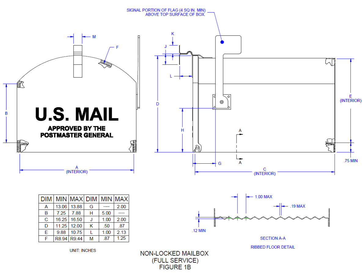
LC – Large Capacity - Full or Limited Service (see 3.1.1, 3.1.1.3 & Figure 1B)
Locked Mailboxes:
LMS – Locked, Mail Slot Design - Full or Limited Service (see 3.1.2, 3.1.2.1 & Figures 2A & 2B)
LLC – Locked, Large Capacity / USPS Security Tested - Full or Limited Service (see 3.1.2, 3.1.2.2 & Figure 3)
1.3 Approved Models
1.3.1 Approved Models – A list of manufacturers whose mailboxes have been approved by the United States Postal Service (USPS) will be published annually in the Postal Bulletin. A copy of the most current list of approved models is also available from the office listed in 1.3.2.
1.3.2 Interested Manufacturers - Manufacturing standards and current information about the manufacture of curbside mailboxes may be obtained by writing to:
USPS ENGINEERING SYSTEMS
DELIVERY AND RETAIL TECHNOLOGY
8403 LEE HIGHWAY
MERRIFIELD, VA 22082-8101
2. APPLICABLE DOCUMENTS
2.1 Specifications and Standards - Except where specifically noted, the specifications set forth herein shall apply to all curbside mailbox designs.
2.2 Government Document - The following document of the latest issue is incorporated by reference as part of this standard.
United States Postal Service
Postal Operations Manual (POM
Copies of the applicable sections of the POM can be obtained from USPS Delivery and Retail, 475 L’Enfant Plaza SW, Washington, D.C. 20260-6200.
2.3 Non-Government Documents - The following documents of the latest issue are incorporated by reference as part of this standard.
American Standards for Testing Materials (ASTM)
ASTM G85 Standard Practice for Modified Salt Spray (Fog) Testing
ASTM D968 Standard Test Methods for Abrasion Resistance of Organic Coatings by Falling Abrasive
Copies of the preceding documents can be obtained from the American Society for Testing and Materials, 100 Barr Harbor Drive, West Conshohocken, PA 19428-2959.
Underwriters Laboratories (UL)
UL 771 Night Depositories (Rain Test Only)
Copies of the preceding document can be obtained from Underwriters Laboratories Inc., 333 Pfingsten Road, Northbrook, IL 60062-2096
3. REQUIREMENTS
3.1 General Design - Mailboxes must meet regulations and requirements as stipulated by USPS collection and delivery, operation and policy (see 2.2). This includes carrier door operation as stated (see 3.3), flag operation (see 3.6), incoming mail openings and the retrieval of outgoing mail (see below in 3.1). The manufacturer determines the opening style, design and size; however, the carrier must be able to deposit the customer’s mail. Outgoing mail for full service designs must be able to be pulled straight out of the mailbox without interference from protrusions, hardware, etc. Mailboxes must be capable of passing the applicable testing requirements (see Section 4). Mailboxes must not be made of any transparent, toxic, or flammable material (see 3.2). The mailbox must protect mail from potential water damage which may result from wet weather conditions (see 4.4). Any advertising on a mailbox or its support is prohibited. Additional specific requirements follow.
3.1.1 Non-Locked Designs (Limited and Full Service) – Mailbox designs that conform to any of the three design types specified in 3.1.1 will be classified as non-locked with the appropriate sub-designation. Designs incorporating a carrier signal flag (see 3.6) will be classified as full service mailboxes. Designs with no flag will be classified as limited service (see 3.11). As specified in 3.4, a rear door is permitted to enable the customer to remove mail without standing in the street. The use of any ancillary items (i.e., locks, locking devices or inserts) that either require the carrier to use a key to gain access to a non-locked mailbox or that restrict or reduce the interior opening of the mailbox, once the front door has been fully opened, is prohibited. There is no local Postmaster approval exception for this prohibition.
3.1.1.1 Traditional Designs (Limited and Full Service) – Mailbox designs that conform to Figure 1A and meet the limited capacity requirements specified in 4.2.1 will be classified as Traditional (T).
3.1.1.2 Contemporary Designs (Limited and Full Service) – Mailbox designs that do not conform to dome-rectangular shape of Traditional designs but meet the limited capacity requirements specified in 4.2.1, while not exceeding the maximum dimensions of Figure 1A, will be classified as Contemporary (C).
3.1.1.3 Large Capacity Designs (Limited and Full Service) – Mailbox designs that conform to Figure 1B and meet the expanded capacity requirements specified in 4.2.2 will be classified as Large Capacity (LC).
3.1.2 Locked Designs – Mailbox designs that conform to either of the two design types specified in 3.1.2 will be classified as Locked with the appropriate sub-designation.
3.1.2.1 Locked, Mail Slot Designs (Limited and Full Service) – Mailbox designs that conform to either Figure 2A or 2B and meet the limited-capacity requirements specified in 4.2.1 will be classified as Locked, Mail Slot Design (LMS). This locking design option provides non-USPS-tested security for customer’s incoming mail. Although the shape and design are less restrictive, these Locked mailbox designs must meet the same applicable functional requirements. Designs having a slot for incoming mail must be at least 1.75 inches high by 10 inches wide. If a slot has a protective flap, it must operate inward to ensure mail can be inserted in horizontal manner without requiring any additional effort by the carriers (see Figure 2B). The slot must be positioned on the front side of the mailbox facing the street. In addition, the slot must be clearly visible and directly accessible by mail carriers. Any designs that allow for outgoing mail must meet all applicable requirements of this standard.
3.1.2.1.1 Full Service – Locked mailbox designs of this class allow for both incoming and outgoing mail as depicted in Figure 2A. Both incoming and outgoing mail functionality must be located behind a single carrier service door as shown in Figure 2A. While it is preferred that the outgoing mail function be handled via use of the backside of the front door, any alternate use of a separate outgoing mail compartment, such as beneath or side-by-side with the incoming mail compartment, is permitted provided that no additional carrier service is introduced. All designs must allow the carrier direct access to grasp and retrieve the outgoing mail.
3.1.2.1.2 Limited Service – Locked mailbox designs of this class allow only for incoming mail as shown in Figure 2B.
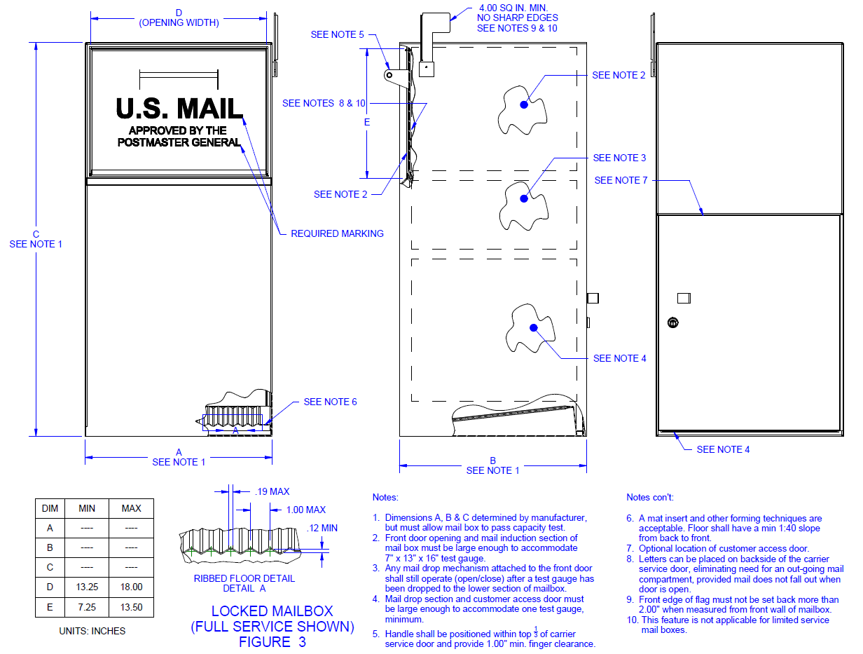
3.1.2.2 Locked, Large Capacity / USPS-Security-Tested Designs (Limited and Full Service) – Mailbox designs that conform to Figure 3 and meet both the expanded capacity requirements specified in 4.2.2 and security testing specified in 4.12 will be classified as Locked, Large Capacity/USPS-Security-Tested (LLC).
3.1.2.2.1 Full Service – Locked mailbox designs of this class allow for both incoming and outgoing mail as depicted in Figure 3. Both incoming and outgoing mail functionality must be located behind a single carrier service door as shown in Figure 3. While it is preferred1 that the outgoing mail function be handled via use of the backside of the front door, any alternate use of a separate outgoing mail compartment, such as beneath or side-by-side with the incoming mail compartment, is permitted provided that no additional carrier service is introduced. All designs must allow the carrier direct access to grasp and retrieve the outgoing mail.
3.1.2.2.2 Limited Service – Locked mailbox designs of this class allow only for incoming mail. Refer to the two Locked mailbox feature exceptions linked to Note 10 of Figure 3.
3.1.3 Mailbox Accessories – Decorative art and devices can be attached to the exterior of approved mailbox designs provided they do not interfere with mail delivery or present a safety hazard. Devices can also be mounted in the interior of approved mailboxes, provided they do not cause the intended mailbox to fail either capacity test described in 4.2, and do not interfere with mail delivery or present a safety hazard. Any advertising on a mailbox or its support is prohibited. Unrestricted spring-loaded devices and designs are prohibited. Auxiliary flags or devices used to signal the customer that the mail has arrived must operate automatically without requiring additional carrier effort.
3.2 Materials - Ferrous or nonferrous metal, wood (restrictions apply), plastic, or other materials may be used, as long as their thickness, form, mechanical properties, and chemical properties adequately meet the operational, structural, and performance requirements set forth in this standard. Materials used must not be toxic, flammable or transparent.
3.2.1 Mailbox Floor - The entire bottom area of all mailboxes, where mail would rest, must be fabricated to prevent mail from damage due to condensation or moisture. Except for the internal mail compartment of locked style mailboxes, all designs must not present a lip or protrusion that would prevent the mail from being inserted or pulled straight out of the mailbox. The surface of the floor cannot be made of wood material. The floor shall be ribbed as shown in Figures 1A, 1B, 2A, 2B and 3 or dimpled, embossed, or otherwise fabricated provided the resulting surface area (touching mail) does not exceed the boundary of a square with sides of 0.25 inch (per dimple or impression) and is a minimum of 0.12 inch high on centers not exceeding 1 inch. A mat insert having a raised surface contour may be used for the internal mail compartment of locked style mailboxes only (see Figure 2A, 2B and 3).
3.2.2 Carrier Signal Flag – The carrier signal flag cannot be made of wood. Plastic is the preferred material.
3.2.3 Door Handle – The door handle cannot be made of wood. Plastic is the preferred material.
3.3 Carrier Service Door –There must be only one carrier service door that must provide access for mail delivery and collection intended by the unit and meet USPS delivery operational requirements (see 2.2). The door must meet the applicable testing requirements specified in 4.3. The carrier service door must operate freely and solely by pulling outward and downward with a convenient handle or knob. The design of the door, including hinges and handles, must provide protection against wind, rain, sleet, or snow (see 4.4). Door latches must hold the door closed but allow easy opening and closing requiring no more than 5 pounds of force. The action of the latch must be a positive mechanical one not relying solely on friction of the hinge parts. The door shall not be spring-loaded. Magnetic latches are acceptable provided adequate closure power is maintained during ambient conditions specified in 4.7 and applicable testing described in Section 4. It is preferred that by either tactile sensation or sound (i.e., a snap or click) carriers are alerted that the door is properly shut. The door, once opened, must remain in the open position until the carrier pushes it closed. The door must rotate a minimum of 100 degrees when opened and it is preferred that the maximum rotation be limited to 120 degrees or less. When in a fully opened and rest position, the opening angle of the door cannot measure more than 180 degrees. No protrusions other than the handle/knob, door catch, alternate flag design, decorative features or markings are permitted on the carrier service door. Protrusions of any kind that reduce the usable volume within the mailbox when closed are not acceptable. See 3.1.2 for carrier service door requirements for Locked mailbox designs.
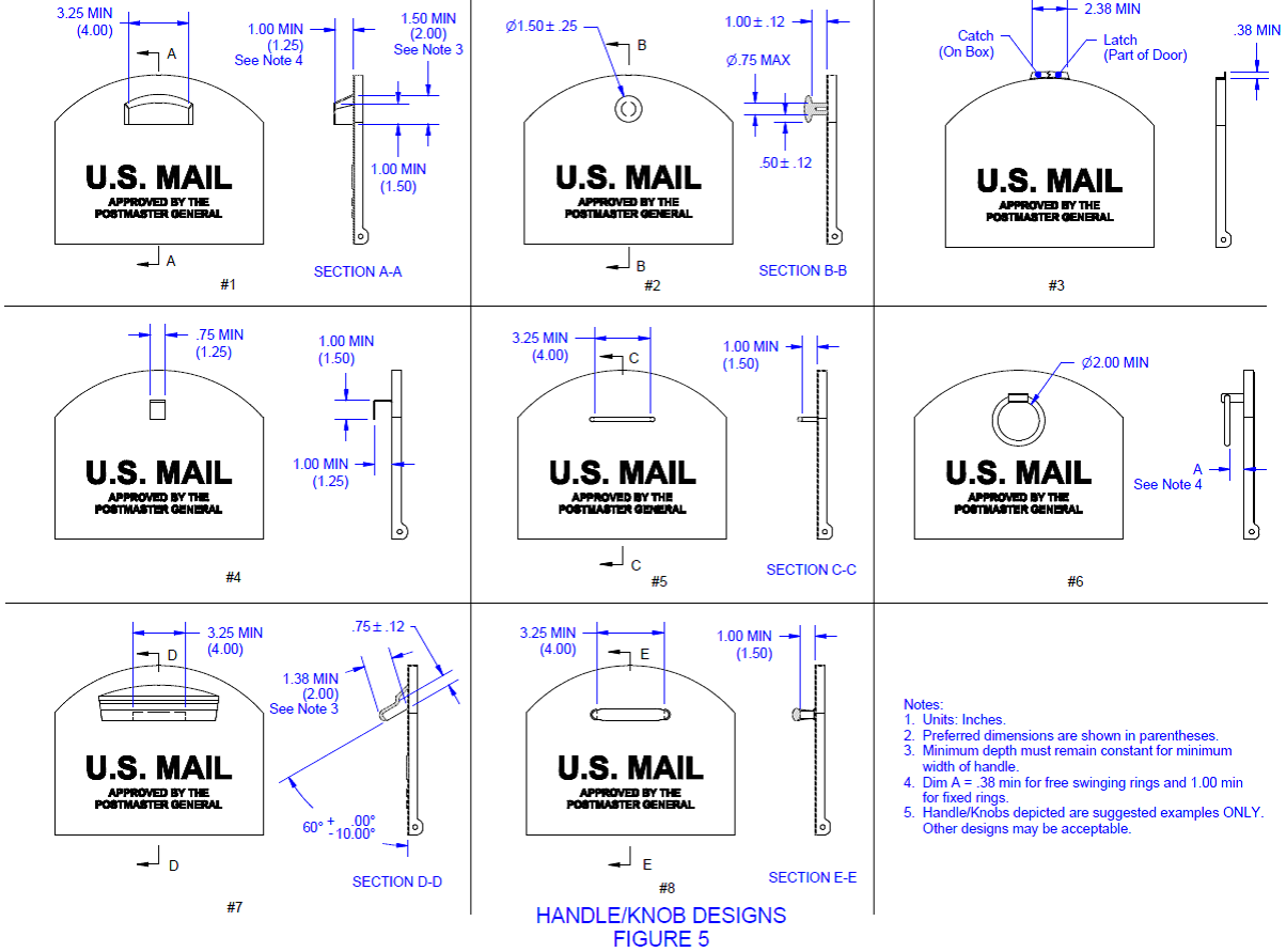
3.3.1 Handle/Knob - The handle or knob shall have adequate accessibility to permit quickly grasping and pulling it with one hand (with or without gloves) to open the door. The handle or knob must be located within the top 1/3 of the door. Various acceptable handle and knob designs with required dimensions are depicted in Figure 5. Other designs may be acceptable provided they allow enough finger clearance and surface area for carriers to grasp.
3.4 Rear Doors – Both locking and non-locking mailbox designs may have rear doors.
3.4.1 Non-Locking Mailbox Designs – These mailbox designs may have a rear door, provided that it does not interfere with the normal delivery and collection operation provided by the carrier, require the carrier to perform any unusual operations or prevent the applicable capacity test gauge from fully inserting. The rear door must not be susceptible to being forced open as a result of large mail items such as newspapers and parcels being inserted through the carrier service door. The rear door must meet the applicable testing requirements specified in Section 4.
3.4.2 Locking Mailbox Designs – These designs must have a customer access door that may be located as shown in Figures 2A, 2B and 3 on the rear wall of the mailbox. However, for locking mailbox designs, the customer access door may be located on a side wall. For locking designs submitted for approval under 3.1.2.2, this door must be subject to the security test requirement in 4.12.
3.5 Locks – Locked mailbox designs, which are submitted for approval under 3.1.2.2, must meet the security test requirements of 4.12 to ensure that incoming mail is only accessible by the customer to the performance level required. The use of locks on all non-locked mailbox designs is prohibited. Manufacturers must include the following statement in their instructions to customers:
IT IS IMPORTANT TO NOTE THAT IT IS NOT THE RESPONSIBILITY OF MAIL CARRIERS TO OPEN MAILBOXES THAT ARE LOCKED, ACCEPT KEYS FOR THIS PURPOSE, OR LOCK MAILBOXES AFTER DELIVERY OF THE MAIL.
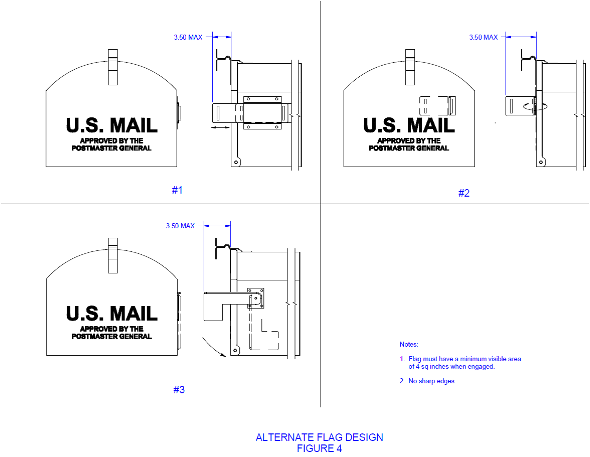
3.6 Carrier Signal Flag – Non-locked and locked mailbox designs classified as Full Service must have a carrier signal flag. While it is preferred that the flag design be one of the approved concepts depicted in Figures 1A, 1B, 2A, 3, and 4, alternates must be considered for approval if all other dimensional and test requirements are otherwise met. As shown in each figure, the flag must be mounted on the right side when facing the mailbox from the front. The flag must not require a lift of more than 2 pounds of force to retract. Additionally, when actuated (signaling outgoing mail), the flag must remain in position until retracted by the carrier. The color of the flag must be in accordance with requirements described in 3.9. The operating mechanism of the flag must not require lubrication and must continue to operate properly and positively (without binding or excessive free play) after being subjected to the test described in Section 4. Optionally, the flag may incorporate a self-lowering feature that causes it to automatically retract when the carrier service door is opened provided no additional effort is required of the carrier. The self-lowering feature cannot present protrusions or attachments and must not interfere with delivery operations in any manner or present hazardous features as specified in 3.1.
3.7 Marking - The mailbox must bear two inscriptions on the carrier service door: "U.S. MAIL" in a minimum of 0.50 inch-high letters and "Approved By The Postmaster General" in a minimum of 0.18 inch high letters. These inscriptions may be positioned beneath the incoming mail slot for Limited Service Locked (Mail Slot Design) mailboxes as shown in Figure 2B. Markings must be permanent and may be accomplished by applying a decal, embossing on sheet metal, raised lettering on plastic, engraving on wood or other methods that are suitable for that particular unit. The manufacturer’s name, address, date of manufacture (month and year), and model number or nomenclature must be legible and permanently marked or affixed on a panel (rear, backside of door, bottom or side interior near the carrier service door) of the mailbox that is readily accessible and not obscured.
3.7.1 Modified Mailbox Marking - Mailboxes that use previously approved units in their design must include marking stating the new manufacturer’s name, address, date of manufacture and model nomenclature in a permanent fashion and location as described in 3.7. Additionally, the "U.S. MAIL" and "Approved By The Postmaster General" marking must be reapplied if it is obscured or obliterated by the new design.
3.8 Coatings and Finishes – The choice of coatings and finishes is optional, provided all requirements of this standard are met. All coatings and finishes must be free from flaking, peeling, cracking, crazing, blushing, and powdery surfaces. Coatings and finishes must be compatible with the mailbox materials. Except for small decorative accents, mirror-like coatings or finishes are prohibited. The coating or finish must meet the applicable testing requirements described in 4.6.
3.9 Color - The color of the mailbox and flag must be in accordance with the requirements stated in 3.9. The mailbox may be any color. The carrier signal flag can be any color except any shade of green, brown, white, yellow or blue. The preferred flag color is fluorescent orange. Also, the flag color must present a clear contrast with predominant color of the mailbox.
3.10 Mounting - The mailbox must be provided with means for convenient and locked mounting that meets all applicable requirements. The manufacturer may offer various types of mounting accessories such as a bracket, post or stand. Although the Postal Service does not regulate the design of mounting accessories, no part of the mounting accessory is permitted to project beyond the front of the mounted mailbox. Mounting accessories must not interfere with delivery operations as described in 3.1.3 or present hazardous features as described in 3.13. See Section 8 for additional important information.
3.11 Instructions and Product Information
3.11.1 Assembly and Installation - A complete set of instructions for assembling and mounting the mailbox must be furnished with each unit. The instructions must include the following conspicuous message:
CUSTOMERS ARE REQUIRED TO CONTACT THE LOCAL POST OFFICE BEFORE INSTALLING THE MAILBOX TO ENSURE ITS CORRECT PLACEMENT AND HEIGHT AT THE STREET. GENERALLY, MAILBOXES ARE INSTALLED AT A HEIGHT OF 41 – 45 INCHES FROM THE ROAD SURFACE TO EITHER THE INSIDE SURFACE OF THE MAILBOX THAT THE MAIL IS PLACED ON BY THE CARRIER OR TO THE LOWEST EDGE OF MAIL ENTRY (FOR LOCKED MAIL SLOT DESIGNS) AND ARE SET BACK 6 – 8 INCHES FROM THE FRONT FACE OF CURB OR ROAD EDGE TO THE MAILBOX DOOR.
3.11.2 Limited Service Mailboxes – The following conspicuous note must be included with each mailbox:
THIS IS A LIMITED SERVICE MAILBOX (WITHOUT FLAG) AND IT IS ONLY INTENDED FOR CUSTOMERS WHO DO NOT WANT POSTAL CARRIERS TO PICK-UP THEIR OUTGOING MAIL. UNLESS POSTAL CARRIERS HAVE MAIL TO DELIVER, THEY WILL NOT STOP AT LIMITED SERVICE MAILBOXES.
3.12 Newspaper Receptacles - A receptacle for the delivery of newspapers may be attached to the post of a curbside mailbox provided no part of the receptacle interferes with the delivery of mail, obstructs the view of the flag, or presents a hazard to the carrier or the carrier’s vehicle. The receptacle must not extend beyond the front of the box when the door is closed. No advertising may be displayed on the outside of the receptacle, except the name of the publication. If the mailbox design does not require a post, a separate mounting arrangement must be made.
3.13 Workmanship - The mailbox must be properly assembled and utilize the best commercial practice workmanship standards in the fabrication of all components and assemblies. All movable parts must fit and operate properly with no unintended catch or binding points. The unit must be free from harmful projections or other hazardous devices. The unit must not have any sharp edges, sharp corners, burrs or other features (on any surfaces) that may be hazardous to carriers or customers, or that may interfere with delivery operations as described in 3.1.
3.14 Intellectual Property – Under no circumstances does the Postal Service intend that manufacturers use third-party intellectual property without an appropriate license agreement between the manufacturer and the third party at issue. The manufacturer is solely responsible for obtaining any necessary licenses and is solely responsible for any liability incurred in connection with any intellectual property infringement allegations concerning devices that the USPS reviews and approves. The manufacturer agrees not to use any USPS marks, including but not limited to APPROVED BY THE POSTMASTER GENERAL or USPS-APPROVED, without prior USPS approval and a license from the USPS.
4. TESTING REQUIREMENTS
4.1 Testing Requirements - Mailboxes will be subjected to all applicable testing described herein (specific requirements follow). A mailbox that fails to pass any test will be rejected. Testing will be conducted in sequence as listed herein and in Table III.
4.2 Capacity – Non-locked and locked designs must meet the applicable minimum capacity requirements as tested by insertion and removal of a test gauge or appropriate mail test items as specified in 4.2.1 and 4.2.2.
4.2.1 Capacity (Limited Capacity Test Gauge) – Traditional and Contemporary designs, submitted for approval under 3.1.1.1 and 3.1.1.2, must meet minimum capacity requirements tested by insertion and removal of a standard test gauge which measures 18.50 inches long x 5.00 inches wide x 6.00 inches high. The test gauge is inserted with its 6-inch dimension aligned in the vertical axis (perpendicular to the mailbox floor). The gauge must be capable of easy insertion and removal; and while inserted, allow for all doors to be completely closed without interference.
The capacity of Locked designs, submitted for approval under 3.1.2.1, which have slots, chutes or similar features, will be tested and approved based upon whether standard USPS mail sizes (see Table I) can be easily inserted through the mail slot or opening. Retrieval of this mail from the locked compartment shall be equally as easy.
TABLE I
Standard Mail (Locked Designs)
|
Description |
Size (L x H x Thk) (inches) |
|---|---|
Express & Priority Mail Envelopes |
12 1/2 x 9 1/2 x 1/2 |
Priority Mail Box |
8 5/8 x 5 3/8 x 1 5/8 |
4.2.2 Capacity (Expanded Capacity Test Gauge) – Non-Locked and Locked designs, submitted for approval to either 3.1.1.3 or 3.1.2.2, must meet minimum capacity requirements tested by insertion and removal of a standard test gauge which measures 16.00 inches long x 13.00 inches wide x 7.00 inches high. The test gauge is inserted with its 7-inch dimension aligned in the vertical axis (perpendicular to the mailbox floor). The gauge must be capable of easy insertion and removal; and while inserted, allow for the door(s) to be completely closed without interference. The capacity of Locked designs must also meet this capacity test requirement; however, any dimension may be aligned in the vertical axis. Retrieval of the test gauge from the locked compartment must be equally as easy.
4.3 Operational Requirements - Carrier service doors, auxiliary doors, door catches/mechanisms, carrier signal flags and applicable accessory devices must be capable of operating 7,500 normal operating cycles (1 cycle = open/close) at room temperature, continuously and correctly, without any failures such as breakage of parts. Testing may be performed either manually or by means of an automated mechanically driven test fixture which essentially mimics a manual operation. This test applies to all mailbox designs.
4.4 Water-Tightness – A rain test in accordance with UL 771, section 47.7 must be performed to determine a mailbox’s ability to protect mail from water. The rain test must be operated for a period of 15 minutes for each side. At the conclusion of the test, the outside of the unit is wiped dry and all doors are opened. The inside of the compartment must contain no water other than that produced by high moisture condensation. This test applies to all mailbox designs.
4.5 Salt Spray Resistance - A salt spray test must be conducted in accordance with method A5 of ASTM G85, Standard Practice for Modified Salt Spray (Fog) Testing. The salt test must be operated for 25 continuous cycles with each cycle consisting of 1-hour fog and 1-hour dry-off. The mailbox must be tested in a finished condition, including all protective coating, paint, and mounting hardware and must be thoroughly washed when submitted to remove all oil, grease, and other nonpermanent coatings. No part of the mailbox may show finish corrosion, blistering or peeling, or other destructive reaction upon conclusion of test. Corrosion is defined as any form of property change such as rust, oxidation, color changes, perforation, accelerated erosion, or disintegration. The build-up of salt deposits upon the surface will not be cause for rejection. However, any corrosion, paint blistering, or paint peeling is cause for rejection. This test is primarily applicable to ferrous metal mailbox designs. The test is also valid for mailbox designs made of plastic, wood, or other materials that use any metal hardware.
4.6 Abrasion Resistance – The mailbox’s coating or finish must be tested for resistance to abrasion in accordance with method A of ASTM D968. The rate of sand flow must be 2 liters of sand in 22 +3 seconds. The mailbox will have failed the sand abrasion test if it requires less than 15 liters of sand to penetrate its coating, or if it requires less than 75 liters of sand to penetrate its plating. This test applies to metal mailbox designs only.
4.7 Temperature Stress Test – The mailbox under test must be placed in a cold chamber at -65° Fahrenheit for 24 hours. The chamber must first be stabilized at the test temperature. After remaining in the -65° environment for the 24-hour period, the unit must be quickly removed from the cold chamber into room ambient and tested for normal operation. The removal from the chamber and the testing for normal operation must be accomplished in less than 3 minutes. The room ambient must be between 65° and 75° Fahrenheit. Normal operation is defined as operation required and defined by this document. The unit under test must undergo a similar temperature test, as described above, at a temperature of 140° Fahrenheit. This test applies to all mailbox designs.
4.8 Structural Rigidity Requirements – Forces of specified magnitude (see Table II) must be slowly applied at specific points on the mailbox under test (see Figure 6). These forces must be held for a minimum of 1 minute and then released. After their release, the deformation caused by the forces must be measured. If the deformation exceeds the limit specified in Table II, the mailbox under test has failed to meet the structural rigidity requirement. The doors must remain closed for test positions 1 through 6. The forces at positions 1 and 2 must be applied with the mailbox in its normal upright position, supported by a horizontal board. The forces at positions 3, 4, and 5 must be applied with the mailbox lying on its side (flag side down). The mailbox must be supported, on the flag side, by a flat board that is relieved in the immediate area of the flag mechanism. The force at position 6 (Non-Locked mailbox flags only) must be applied with the mailbox lying on its side (flag side up). This load may be applied as shown in Figure 5 or from the other direction. If visible cracks in the material develop as a result of the testing, the mailbox under test has failed to meet the structural rigidity requirement. At the conclusion of the Structural Rigidity testing, if the mailbox under test fails to operate normally, as defined by this document, the mailbox under test has failed to meet the structural rigidity requirement. This test applies to all mailbox designs.
TABLE II
Permanent Deformation Limits
Position |
Deformation (inches) |
Load (pounds) |
|---|---|---|
1 |
1/8 |
200 |
2 |
1/8 |
200 |
3 |
1/8 |
50 |
4 |
1/8 |
50 |
5 |
1/8 |
100 |
6 |
1/2 |
2 |
4.9 Impact Test - Refer to the Figure 6 for load positions. Precondition the mailbox for 4 hours at -20° Fahrenheit. The following testing must be performed within 3 minutes of removing the mailbox from the temperature chamber. At both load positions 3 and 4, with the mailbox lying on its side (flag side down) with all doors closed, apply an impact load force generated by a 10-pound weight dropped from a height of 3-feet above the mailbox surface onto a bolster plate having a surface not larger than 2 inches by 6 inches. The mailbox must be supported, on the underside, by a flat board that is relieved in the immediate area of the flag mechanism. If any noticeable perforation, occurrence of sharp edges, or cracking of the material (either inside or outside the mailbox) develops as a result of the impact, or if the door becomes inoperable or fails to close normally, the mailbox under test has failed to meet the impact resistance requirement. This test applies to all mailbox designs.
4.10 Door Catch/Mechanism Test – Door catches/mechanisms must be tested to demonstrate that a force not greater than 5 pounds or less than 1 pound is required to open and close them (see 3.3). A force measurement device must be attached to the front door’s knob or handle. The load must be applied slowly in a direction perpendicular to the plane of the door. The device must allow for the measured force limits to be recorded accurately.
4.11 Carrier Signal Flag Test – The mailbox flag must be tested to demonstrate that a force not exceeding 2 pounds is required to deploy, extend, raise or retract it. The load must be applied at the flag edge furthest from the hinged end or at the leading edge, if the flag retracts and extends. A force measurement device must be attached to the flag so as to apply the load and allow for it to be recorded accurately.
4.12 Security Test (Locked, Large Capacity Designs) – Locked design mailboxes, submitted for 3.1.2.2 approval, must be tested as described below for resistance to tampering and unauthorized entry through the use of tools such as screwdrivers, flat plates, knives, pry bars, vise grips, pliers, chisels, and punches for a period not to exceed 3 minutes for each feature tested. Pry tools used for testing must not exceed 12 inches in length.
4.12.1 Customer Access Door – Gaps and seams around the perimeter of the customer access door must be tested using pry tools listed in 4.12 for a period not to exceed 3 minutes to ensure that access to the compartment cannot be gained within that period of time.
4.12.2 Carrier Access Door – A manual test must be conducted for a period of 3 minutes to ensure that no customer mail items can be accessed and removed through an opened carrier access door within that period of time. No tools are to be used in the performance of this test.
5. QUALITY MANAGEMENT SYSTEM PROVISIONS
5.1 Quality System – The approved source must ensure and be able to substantiate that manufactured units conform to requirements and match the approved design.
5.2 Inspection – The USPS reserves the right to inspect units for conformance at any stage of manufacture. Inspection by the USPS does not relieve the approved source of the responsibility to provide conforming product. The USPS, may, at its discretion, revoke the approval status of any product that does not meet the requirements of this standard.
5.3 System – The approved source must use a documented quality management system acceptable to the USPS. The USPS has the right to evaluate the acceptability and effectiveness of the approved source’s quality management system prior to approval, and during tenure as an approved source. At a minimum, the quality management system must include controls and record keeping in the areas described in 5.3.1 through 5.3.8.
5.3.1 Document Control – Documents used in the manufacture of product must be controlled. The control process for documents must ensure the following:
5.3.2 Supplier Oversight – The approved source must use a documented process that ensures the following:
5.3.3 Inspection and Testing – The approved source must monitor and verify that product characteristics match approved design. This activity must be carried out at appropriate stages of manufacture to ensure that only acceptable products are delivered.
5.3.4 Control of Nonconforming Product – The control method and disposition process must be defined and ensure that any product or material that does not conform to the approved design is identified and controlled to prevent its unintended use or delivery.
5.3.5 Control of Inspection, Measuring, and Test Equipment – The approved source must ensure that all equipment used to verify product conformance is controlled, identified, and calibrated at prescribed intervals traceable to nationally recognized standards in accordance with documented procedures.
5.3.6 Corrective Action – The approved source must maintain a documented complaint process. This process shall ensure that all complaints are reviewed and that appropriate action is taken to determine cause and prevent reoccurrence. Action must be taken in a timely manner and be based on the severity of the nonconformance. In addition to outlining the approved source’s approach to quality, the documentation must specify the methodology used to accomplish the interlinked processes and describe how they are controlled. The approved source must submit its quality documentation to the Postal Service for review along with the preliminary design review.
NOTE: It is recognized that each approved source functions individually. Consequently, the quality system of each approved source may differ in the specific methods of accomplishment. It is not the intent of this standard to attempt to standardize these systems, but to present the basic functional concepts that when conscientiously implemented will provide assurance that the approved source’s product meets the requirements and fully matches the approved design.
5.3.7 Documentation Retention – All of the approved source’s documentation pertaining to the approved product must be kept for a minimum of 3 years after shipment of product.
5.3.8 Documentation Submittal – The approved source must submit a copy of their quality system documentation relevant to the manufacture of curbside mailboxes for review as requested during the approval process and tenure as an approved source.
6. APPLICATION REQUIREMENTS
6.1 Application Requirements – All correspondence and inquiries must be directed to the address in 1.3.2. The application process consists of the steps described in 6.1.1 through 6.1.3.4.
6.1.1 Preliminary Review – Manufacturers must first satisfy requirements of a preliminary review prior to submitting samples of any sample mailboxes or accessories. The preliminary review consists of a review of the manufacturer's conceptual design drawings for each mailbox for which the manufacturer is seeking approval. Computer-generated drawings are preferred, but hand-drawn sketches are acceptable provided they adequately depict the overall shape and interior size of the proposed mailbox design. Drawings must also include details about the design of applicable features such as the carrier service door (including the mail drop design and mechanism, for locking mailboxes), latch, handle, flag, floor and mail induction opening size. If drawings show that the proposed mailbox design appears likely to comply with the requirements of this standard, manufacturers will be notified in writing and may then continue with the application requirements described in 6.1.2. Do NOT submit any sample units to the USPS prior to complying with the requirements of 6.1.2. Notification that a manufacturer’s drawings satisfy the requirements of the preliminary review does NOT constitute USPS approval of a design and must NOT be relied upon as an assurance that a design will ultimately be approved.
6.1.2 Independent Lab Testing – Upon receiving written notification from the USPS that a submitted design satisfies requirements of the preliminary review, manufacturers must, at their own expense, submit one representative sample of their mailbox or accessory for which the vendor seeks USPS approval to an independent laboratory for testing along with a copy of the preliminary review letter from the USPS. Manufacturers with more than one unique model must have each one tested independently. Models that are generally of the same size, shape, and material of previously approved designs but only have different decorative features (i.e., color scheme and surface contours) are not considered unique and do not require any testing. Manufacturers seeking approval of models that are not unique must submit documentation for each model in accordance with 6.1.3.2. This documentation must be reviewed and the proposed model must either be approved or disapproved (see Section 7). All tests must be performed by an approved independent test lab, except for the security tests, which must be performed by the Postal Service. See Appendix A for information on how to receive the list of USPS-approved independent test labs.
6.1.3 Final Review – Within one year of receipt of USPS preliminary review approval, manufacturers must submit one sample mailbox or accessory to the USPS for security testing (if applicable), final review, and approval. The sample must be accompanied with a certificate of compliance and a copy of the laboratory test results (see 6.1.3.3). Mailboxes submitted to the USPS (see 1.3.2) for final evaluation must be identical in every way to the mailboxes to be marketed, and must be marked as specified in 3.7. Manufacturers may be subject to a verification of their quality system prior to approval. This may consist of a review of the manufacturer's quality manual (see 6.1.3.4) and an onsite quality system evaluation (see 5.2). If this final review submission does not occur within the prescribed timeframe, the preliminary review approval must be rescinded.
6.1.3.1 Installation Instructions – Manufacturers must furnish a written copy of their installation instructions for review. These instructions must contain all information as detailed in 3.11.
6.1.3.2 Documentation – Units submitted for approval must be accompanied by one complete set of manufacturing drawings consisting of black on white prints (blueprints or sepia are unacceptable). The drawings must be dated and signed by the manufacturer’s representatives. In addition, a second complete drawing set must be provided in electronic form. This drawing set does not have to be images of the signed drawings. The drawings must completely document and represent the design of the unit tested. If other versions of the approved mailbox are to be offered, the drawings must include the unique or differing design items of these versions. The drawings must include sufficient details to allow the USPS to inspect all materials, construction methods, processes, coatings, treatments, finishes (including paint types), control specifications, parts, and assemblies used in the construction of the unit. Additionally, the drawings must fully describe any purchased materials, components, and hardware including their respective finishes. The USPS may request individual piece parts to verify drawings.
6.1.3.3 Certification of Compliance & Test Results – Manufacturers must furnish a written certificate of compliance indicating that their design fully complies with the requirements of this standard. In addition, the manufacturer must submit the lab’s original report which clearly shows results of each test conducted (see Table III). The manufacturer bears all responsibility for its units meeting these requirements and the USPS reserves the right to retest any and all units submitted, including those which are available to the general public. Any changes to the design after approval and certification must be submitted to the USPS for evaluation.
TABLE III
Test Requirements
|
Test |
Requirement |
Reference |
Applicable Document |
|---|---|---|---|
Capacity |
Insertion of test gauge |
4.2 |
|
Operational Requirements |
7,500 cycles |
4.3 |
|
Water-Tightness |
No appreciable moisture |
4.4 |
UL 771, Section 47.7 |
Salt Spray Resistance |
25 cycles |
4.5 |
ASTM G85 |
Abrasion Resistance |
75 liters |
4.6 |
ASTM D968 |
Temperature Stress Test |
Must function between –65° F and 140° F |
4.7 |
|
Structural Rigidity Requirements |
Refer to Table II for loads and points, maximum 1/8 inch permanent deformation |
4.8 |
|
Impact Test |
10 lbs. dropped from 3 feet |
4.9 |
|
Door Catch/ Mechanism Test |
Max 5 lbs. / Min 1 lb. to open/close door |
4.10 |
|
Carrier Signal Flag Test |
Max 2 lbs required to use flag |
4.11 |
|
6.1.3.4 Quality Policy Manual – Manufacturer must submit its quality policy manual to the address listed in 1.3.2.
7. APPROVAL OR DISAPPROVAL
7.1 Disapproval – Written notification, including reasons for disapproval, will be sent to the manufacturer within 30 days of completion of the final review of all submitted units. All correspondence and inquiries shall be directed to the address listed in 1.3.2.
7.1.1 Disapproved Mailboxes – Mailboxes disapproved will be disposed of in 30 calendar days from the date of the written notification of disapproval or returned to the manufacturer, if requested, provided the manufacturer pays shipping costs.
7.2 Approval – One set of manufacturing drawings with written notification of approval will be returned to the manufacturer. The drawings will be stamped and identified as representing each unit.
7.2.1 Approved Mailboxes – Mailboxes that are approved will be retained by the USPS.
7.2.2. Rescission – The manufacturer’s production units must be constructed in accordance with the USPS-certified drawings and the provisions of this specification and be of the same materials, construction, coating, workmanship, finish, etc., as the approved units. The USPS reserves the right at any time to examine and retest units obtained either in the general marketplace or from the manufacturer. If the USPS determines that a mailbox model is not in compliance with this standard or is out of conformance with approved drawings, the USPS may, at its discretion, rescind approval of the mailbox as described in 7.2.2.1 through 7.2.2.5.
7.2.2.1 Written Notification – The USPS will provide written notification to the manufacturer that a mailbox is not in compliance with this standard or is out of conformance with approved drawings. This notification will include the specific reasons that the unit is noncompliant or out of conformance and shall be sent via Registered MailTM.
7.2.2.1.1 Health and Safety – If the USPS determines that the noncompliance or nonconformity constitutes a danger to the health or safety of customers or letter carriers, the USPS may, at its discretion, immediately rescind approval of the unit. In addition, the USPS may, at its discretion, order that production of the mailbox cease immediately, that any existing inventory not be sold for receipt of U.S. mail, and that USPS Approved corrective design changes be applied to sold and unsold units.
7.2.2.2 Manufacturer’s Response – In all cases of noncompliance or nonconformity other than those determined to constitute a danger to the health or safety of customers or letter carriers, the manufacturer must confer with the USPS and must submit one sample of a corrected mailbox to the USPS for approval no later than 45 calendar days after receipt of the notification described in 7.2.2.1. Failure to confer or submit a corrected mailbox within the prescribed period shall constitute grounds for immediate rescission.
7.2.2.3 Second Written Notification – The USPS will respond to the manufacturer in writing, via Registered Mail, no later than 30 calendar days after receipt of the corrected mailbox with a determination of whether the manufacturer’s submission is accepted or rejected and with specific reasons for the determination.
7.2.2.4 Manufacturer’s Second Response – If the USPS rejects the corrected mailbox, the manufacturer may submit a second sample of the corrected mailbox to the USPS for approval no later than 45 calendar days after receipt of the notification described in 7.2.2.3. Failure to confer or submit a corrected mailbox within the prescribed period will constitute grounds for immediate rescission.
7.2.2.5 Final USPS Rescission Notification – The USPS will provide a final response to the manufacturer in writing no later than 30 calendar days after receipt of the second sample corrected mailbox with a determination of whether the manufacturer’s submission is accepted or rejected and with specific reasons for the determination. If the second submission is rejected, the USPS may, at its discretion, rescind approval of the mailbox. In addition, the USPS may, at its discretion, order that production of the mailbox cease immediately, and that any existing inventory not be sold or used for receipt of U.S. Mail. If the USPS rescinds approval, the manufacturer is not prohibited from applying for a new approval pursuant to the provisions of Section 6.
7.2.3 Revisions, Product or Drawings – Changes that affect the form, fit, or function (e.g., dimensions, material, and finish) of approved products or drawings must not be made without written USPS approval. Any proposed changes must be submitted with the affected documentation reflecting the changes (including a notation in the revision area), and a written explanation of the changes. One unit, incorporating the changes, may be required to be resubmitted for testing and evaluation for approval.
7.2.3.1 Corporate or Organizational Changes – If any substantive part of the approved manufacturer’s structure changes from what existed when the manufacturer became approved, the manufacturer must promptly notify the USPS and will be subject to a reevaluation of its approved products and quality system. Examples of substantive structural changes include the following: change in ownership, executive or quality management; major change in quality policy or procedures; relocation of manufacturing facilities; and major equipment or manufacturing process change (e.g., outsourcing vs. in-plant fabrication). Notification of such changes must be sent to the address in 1.3.
7.2.4 Product Brochure – Within 60 days upon sale to the public, manufacturers must submit one copy of their product brochures representing approved mailbox designs to the address listed in 1.3.2 and to:
USPS
Delivery Program Support
475 L’Enfant Plaza SW, Rm 7142
Washington, DC 20260-7142
8. NOTES
8.1 Mailboxes intended to be used in delivery to customers’ doors are not currently “approved” by the United States Postal Service as referenced in this standard. However, it is recommended that these boxes conform to the intentions of this specification, particularly the safety of the carrier and customer and the protection of the mail. The local postmaster must be contacted prior to the installation and use of any door mailbox.
8.2 The United States Postal Service does not approve mailbox posts or regulate mounting of mailboxes other than the requirements specified in 3.10 and 3.11. Please note that mailbox posts are often subject to local restrictions, state laws and federal highway regulations. Further information may be obtained from:
American Association of State Highway and Transportation Officials
444 N. Capitol St. NW, Suite 249
Washington, D.C. 20001-1512
http://www.transportation.org
Federal Highway Administration
Office of Safety
1200 New Jersey Avenue, SE
Washington, D.C. 20590-0001
safety.fhwa.dat.gov


APPENDIX A
USPS-APPROVED INDEPENDENT TEST LABORATORIES
1.) To obtain the latest copy of USPS-approved test labs, contact:
USPS ENGINEERING SYSTEMS
DELIVERY AND RETAIL TECHNOLOGY
8403 LEE HIGHWAY
MERRIFIELD, VA 22082-8101
2.) Additional test laboratories may be added provided they satisfy USPS certification criteria. Interested laboratories should contact:
USPS ENGINEERING
TEST EVALUATION AND QUALITY
8403 LEE HIGHWAY
MERRIFIELD, VA 22082-8101
The term ‘preferred’ as used throughout this document in conjunction with any requirement implies that compliance is desired but not mandatory.